A. Anywhere from 5mm to 30mm is the simple answer. It is advantageous to place the UV LED curing units close to the web material to get maximum energy density onto the substrate and thus faster line speeds. However, at close distances, 5 to 10 mm commonly used in printing applications, the uniformity across the web width is poor. You also risk damage to the UV emission window (and the product) should the web material come into contact and it’s more likely to contaminate the emission window with coating or adhesive. Micro-optics used in Semray UV LED curing systems enable converting line working distances of 20 to 30mm to ensure uniformity across the web width without reducing energy density significantly.
Developing UV LED Curing Processes for Converting Applications
Here are the most common questions we get from process development and design engineers familiar with traditional UV curing technology who are considering UV LED curing for their wide web converting processes such as laminating adhesives (film-to-film, film-to-paper, and film-to-foil), hydrogels (transdermal patches, etc.), nanoimprint lithography, and others.

A. Laminating adhesives (film-to-film, film-to-foil, and film-to-paper), pressure sensitive adhesives, and hydrogels (transdermal patches, etc.), or processes where the UV energy can pass through one side of a substrate such as a transparent film to reach the chemistry beneath or to create patterns (nanoimprint lithography) on the film. UV LED’s monochromatic wavelength output (365nm or 385nm) is similar to iron additive UV curing lamps. So chemistries suitable for these additive lamps can likely be used or used with slight reformulating.

A. No, UV LEDs can be used on lines up to 90 inches wide. UV LED curing system manufacturers either make an array of the length you need or combine smaller arrays of UV LEDs into a single system that can span the width. For example, Semray’s modular plug and play UV LED curing platform uses 3-inch wide segments that mount into a housing or backplane. The backplane has the power and controls and can contain enough segments to span a 90-inch wide converting line.

A. Uniformity across the web width depends on the specific equipment chosen, but generally uniformity is better with UV LEDs the farther away they are from the substrate. Too close and there tend to be “hot spots”. Most converting lines place UV LEDs 10 to 30 mm from the web, but unless particular specialized optical control is employed there will be significantly less UV energy density which reduces line speeds. Micro-optics used in Semray UV LED curing systems enable uniformity across the web width without reducing energy density significantly. Every Segment (consisting of 3 channels) is calibrated before shipment with an accuracy of +/-2% (which is within the measuring tolerance of most UV meters). With this balancing (calibration) we can achieve an overall uniformity within a large system of +/-5%.
A. There is much confusion about how to compare traditional UV lamps to UV LED systems, often because the terminology used is inconsistent or overlapping. In particular for UV LED curing, equipment specifications can vary from manufacturer to manufacturer. This is actually two questions, so let’s take each in turn.
1. Power requirements for UV lamps describe the electrical power input the lamp consumes. You will see this written as Watts or W/inch. Traditional lamps using a quartz bulb to generate UV, specify input power in W/inch. To calculate the total electrical power required to operate the lamp, simply multiply input power by the length of the bulb in inches (30 inch x 600 W/inch = 18,000 Watts). Power is designated this way to make it easy to compare lamps of different lengths.
UV LED curing units cannot use this W/inch specification for input power, because there is no long continuous bulb like there is with traditional systems. Instead, UV LED curing lamps utilize many extremely small LED diodes which are densely packed together in multiple columns and rows called an array, so only Watts are used to specify input power. Typically, UV LED lamp size will be specified by the dimensions of the emission window, the quartz window separating the diodes from open air, and is written in terms of length and width.
In both cases, this input power is for the lamp or array only and does not indicate the total electrical power needed to operate the curing system. Some curing equipment manufacturers include a total power consumption specification, also in Watts, but not all do.
2. The UV output of a lamp is called irradiance (sometimes referred to as intensity) and describes the highest UV energy seen at a given distance from a lamp, making it a very practical value for end users. For traditional systems using elliptical reflectors, the peak irradiance is focused inches away from the bulb. For a UV LED system, the irradiance reported by most manufacturers is measured directly at the emission window face. In both cases, this irradiance is per square inch, Watts/in2, or more often, a per square centimeter value (W/cm2).
The two most important values impacting curing are typically peak irradiance (W/cm2) and total energy (J/cm2), sometimes referred to as dose, which takes into account exposure time. For a specific curing process these measurements need to be taken at the substrate, not the emission window of the UV LED curing unit. End users should take radiometry measurements themselves, using the correct radiometry measurement device for UV LED curing, to characterize the curing parameters for their process. Learn more about correctly measuring output of UV LEDs by downloading Technical Paper: Comparing traditional UV to UV LED .

A. Yes, if current trends continue -- 12% annual increases in UV energy output -- then adopting UV LED curing now may seem risky. However, some UV LED manufacturers offer modular systems which enable upgrading to new modules without replacing the entire system, a significant cost advantage. For example, with Semray UV LED curing modules the LED arrays can be upgraded with latest technology arrays in the future, or with different wavelengths as process needs change without having to change anything else. Learn more about how to “ future proof ” UV LED processes.
A. UV LEDs don’t produce any infrared (IR) heat and operate at 1/10th of the temperature of traditional UV curing lamps. Exactly how much less heat reaches your substrate depends on many factors such as the color of the substrate and UV formulation (dark colors absorb more heat), whether you have chill rolls in place, the speed of your line, and the distance of the UV lamps from the substrate. Generally speaking, running lab tests is the best way to determine whether a heat sensitive substrate can now be cured using UV LEDs.
A. Yes, UV LEDs will operate for 20,000+ hours, but like all UV curing sources they also degrade in output over time, though at a much slower rate than traditional UV curing lamps. Useful lifetime is a more meaningful measure of how long a UV LED will provide sufficient energy output for your curing process. Unfortunately there is not an industry standard that specifies testing conditions and percent energy output reduction to quantify useful lifetime.
In regards to failure mechanism, as individual LED chips fail, surrounding LEDs in the array will self-adjust to compensate or balance the output to maintain a consistent energy output. Of course there reaches a point eventually where the array needs to be replaced either because curing is no longer possible (energy output too low), or because the operating temperatures rise too high eventually shutting down the system. The Semray UV LED system makes replacement easy – just use the quick disconnect to remove a segment (module) and insert a spare one with very little downtime. Meanwhile you can return the segment to have channels (arrays) replaced.
A. Yes, there are many options for running tests with UV LED curing equipment. Lab testing is often a good first place to start so you can get initial feasibility testing without too much expense. Chemistry formulators, UV LED curing equipment manufacturers, and toll coaters usually have the capability to run tests using benchtop or floor standing conveyors with your proposed substrates and formulations. For example, Heraeus Noblelight offers free UV LED curing testing at its Application Text Centers which is staffed with application engineers and chemists who run tests to determine UV LED cure parameters, verify and quantify end properties, and UV LED system requirements. Heraeus Noblelight also loans out Semray UV LED curing equipment, though many UV formulators already have Semray equipment in their labs.
Once you can see firsthand that UV LED curing works in the lab, you’ll likely need assistance incorporating the UV curing system into your converting or laminating process. The next step is typically running trials on a wide web pilot line or a production line at either the customer, converting line equipment manufacturer, or toll coater. This level of testing typically costs significantly more, but provides realistic process parameters for scaling up to a commercial production process and any special design considerations for the UV LED curing system. Results from these tests provide the justification to purchase UV curing equipment. Heraeus Noblelight offers loaner Semray UV LED curing equipment for pilot line or in-plant trials and assistance from applications engineers throughout.
A. Unlike traditional UV curing systems, changing to different wavelengths can be more complicated with UV LEDs, especially for wide web converting lines, unless you choose a modular system. With traditional UV systems, changing wavelengths requires replacing the mercury “H” bulb(s) with an additive bulb(s). However, some wide web UV LED curing systems are built as one long array of LEDs. So to change to a different wavelength would require replacing the entire LED array which would be cumbersome, time consuming, and costly. If you are likely to need the process flexibility of different wavelengths, a modular UV LED system will be much less cumbersome and expensive than a custom array, with less changeover time. For example, Semray’s plug & play UV LED curing platform uses modules that easily unsnap without any tools. Spare modules with different wavelength UV LEDs can be easily and quickly inserted, literally in only seconds each.
UV LEDs can be used in combination with traditional UV curing systems (medium pressure arc or microwave “H” lamps) for applications requiring surface curing. The longer wavelength output of the UV LEDs cure deep to ensure adhesion and curing of thick laminating adhesives and coatings, while the shorter wavelengths of an “H” bulb will provide surface cure properties like that for hard coats on window films. In some situations nitrogen inerting may be used with UV LEDs to reduce oxygen inhibition and improve surface curing.

A. Since UV LED curing systems are solid-state devices without the need for shutters, they are easy to control and integrate into wide web converting line process control schemes. UV LED curing units are controlled by remotely mounted power supplies and optional touch screen interfaces. For flexible processing needs there is typically the ability to control on/off instantly and dimming of output energy down to 40%. Frequent on/off cycles don’t decrease UV LED lifetimes like it does with arc lamp curing systems. In fact, because the UV LED is operating fewer hours, frequent cycling should increase lifetimes. Semray UV LED systems provide the ability to have up to five presets for fast adjustments (dimming, emission width) to meet the process needs of different production runs on the converting or laminating line.
Some UV LED systems do offer self-diagnostics and monitoring to insure proper operation, reduce early failure, enable quick troubleshooting, and ensure consistent output. Semray UV LED curing systems, for example, offer self-regulating cooling to intelligently manage temperatures and increase LED life. Sensors detect and provide warnings if temperatures rise too high and eventually shut down the module to protect the LEDs from damaging temperatures. In addition, individual LED arrays self-balance energy output as individual LED chips fail ensuring consistent output across a segment and across all segments.

A. UV LED curing systems use either water cooling or air cooling to remove heat from the LED arrays. In either case, the cooling needs are significantly less than with mercury arc lamp UV curing systems, so cooling is much simpler. For example, air cooled UV LED curing systems incorporate small internal muffin type fans. So unlike arc lamps, there’s no need for large external blowers and exhaust systems with bulky and costly ducting.
There are limits to the ambient conditions based on surrounding temperatures, humidity, and the maximum volume of cooling air the system provides. For example, Semray UV LED curing systems can operate in ambient conditions between 50°F and 104°F, and a maximum humidity of 80% non-condensing. High levels of ambient dust and particulate matter as well as flammable substances cause increased maintenance and unsafe operational conditions for UV LED curing just as it does for traditional UV curing systems.
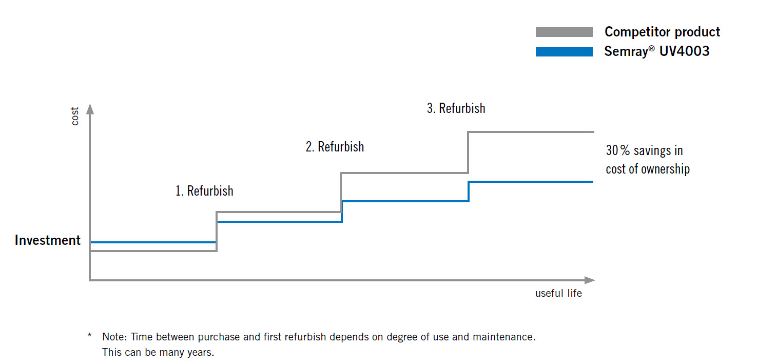
A. Prices for UV LED systems are generally higher than medium pressure arc lamp UV curing systems, though as UV LED curing applications expand, prices are decreasing. Most buyers of UV LED curing equipment base ROI on a combination of cost savings and increased revenues. Cost savings include lower energy costs, less on-going maintenance, and less initial facilities costs (cooling and exhaust blowers, ducting, electrical, light shielding, etc.). Increased revenues are possible due to less downtime , and in some cases, the ability to run new heat sensitive products.